
This section will explain how to draw in the "Walls" layer of your design.
Select the "Walls" layer of your design by clicking on the "Walls" button in the top-left of the ArtiCAD design screen.
In the bottom-left corner of the planning area you will see a green cross. This is your starting point. Your design will always start bottom-left. The outline of your room will draw from the bottom-left towards the top-left of the window. You will then draw the outline clockwise around the design area until you return to your starting point.
It helps to imagine yourself stood in the bottom-left corner, facing the top-left corner, then "walking" around your design, leaving the walls behind you.
You add to the layout of the room by pressing the relevant toolbar button.
An example room can be found here.
Return to top.
The green cross in the bottom left is actually a red cross and a blue cross on top of each other. The red cross will stay at your starting position and the blue cross is your current position on the plan. At the bottom of the design screen it shows the distance between red and the blue cross, broken down into a horizontal and vertical measurement. Distance is the direct distance between the two crosses. The angle is covered in CHAPTER X - ADVANCED STUFF.
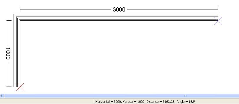
In this example the horizontal distance is 3000, vertical is 1000 and the direct distance is 3162.28.
When the cross goes green you know you have returned to your starting point.
NOTE - the measurement marker only works in Normal Mode. You can still create you room in Drag and Drop mode, but the measurement marker does not update as you draw.
Return to top.
A full list can be found in Appendix 5. ArtiCAD Conventions.
Return to top.

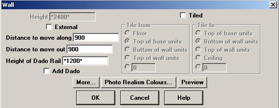
Creates a straight section of wall in the current direction.
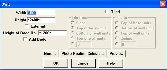
1000 wide wall, turn, 1000 wide wall (external).
Return to top.

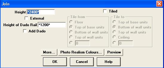
Creates a special section of wall that runs from your current position on the plan back to your starting point.
Should be the last item added to your walls layer. Only one "join" is required.
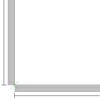
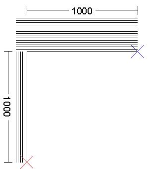
Bottom-left corner of a design without a join and with a join.
NOTE - the green cross. This indicates we have returned to our starting point. However, the bottom corner is missing as we have not joined the walls together.
NOTE - the Join cannot be selected for editing by clicking on it whilst in "Drag and Drop" mode. You must enter "Normal Mode" by either clicking "Mode" - "Normal" or clicking on the "Normal Mode" button on the Utilities Window.
Return to top.
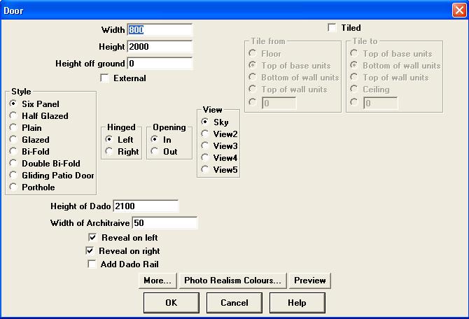
Creates a single doorway. Two doors can be entered side-by-side to create a double/french door.
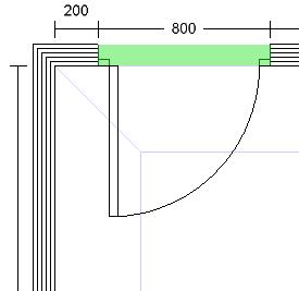
To select a door that is on your design, left-click between the door jams (the green area on the image above).
Return to top.

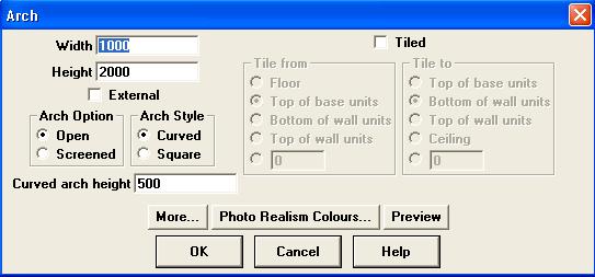
Creates an archway.
Return to top.

Return to top.

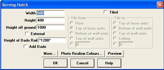
Creates a serving hatch.
Return to top.


Changes the direction of your run of wall items by 90 degrees. A turn/back can be proceeded or followed by any other wall item.
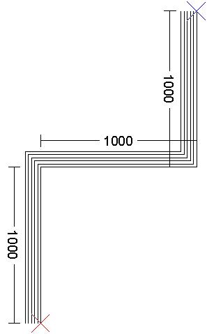
Starting from the red cross - 1000 wall, turn, 1000 wall, back, 1000 wall.
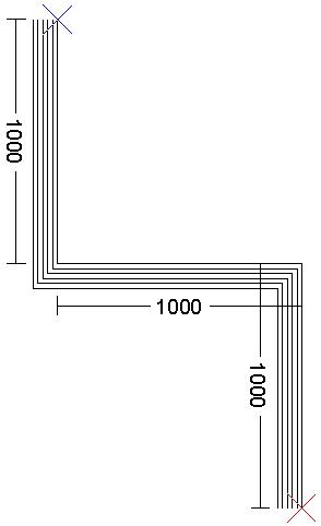
Starting from the red cross - 1000 wall, back, 1000 wall, turn, 1000 wall.
Return to top

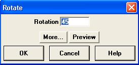
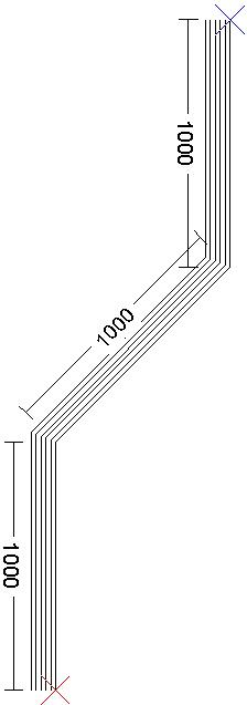
Changes the direction of your run of wall items by a specific angle.
Rotation - the angle through which you wish to turn. Positive values turn clockwise, negative values turn anti-clockwise.
Starting from the red cross - 1000 wall, rotate 45, 1000 wall, rotate -45, 1000 wall.
Starting from the red cross - 1000 wall, rotate -45, 1000 wall, rotate 45, 1000 wall.
A shallow bay window. Starting from the red cross - 500 wall, rotate -30, 500 window, rotate 30, 500 window, rotate 30, 500 window, rotate -30, 500 wall, turn, 2000 wall.
Alternatively you can use the Bay Window wizard. See Bay Window Wizard.
Return to top.

A Point allows you to draw a wall, door, arch or window by specifying the distance along and out of the room. This can be useful if working from scale drawings.
Return to top.


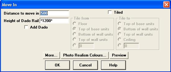
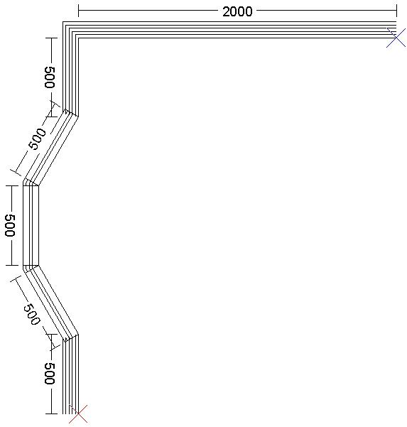
Creates a projection into or out of the current run of wall e.g. a stud wall, pipe boxing, chimney breast..
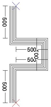
Starting from the red cross - 500 wall, 500 in, 500 wall, 500 out, 500 wall.
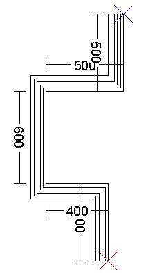
Starting from the red cross - 500 wall, 400 out, 600 wall, 500 in, 500 wall.
Return to top.

Creates a gap in the run of wall. Different to an arch in that there is no lintle or coving drawn across the top to the space.
Return to top.

Stores the current position for use when positioning items. Not required when using Drag and Drop - see Postioning Units With DND.
Return to top.

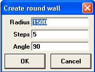
Creates a curved section of wall.
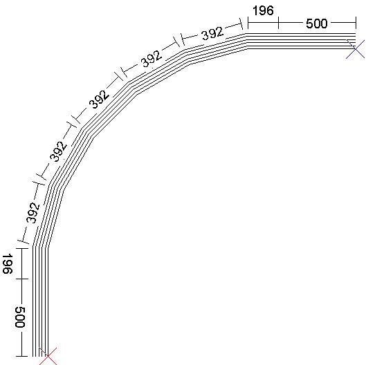
Starting from the red cross - 500 wall, curved wall (radius 1500, steps 5, angle 90), 500 wall.
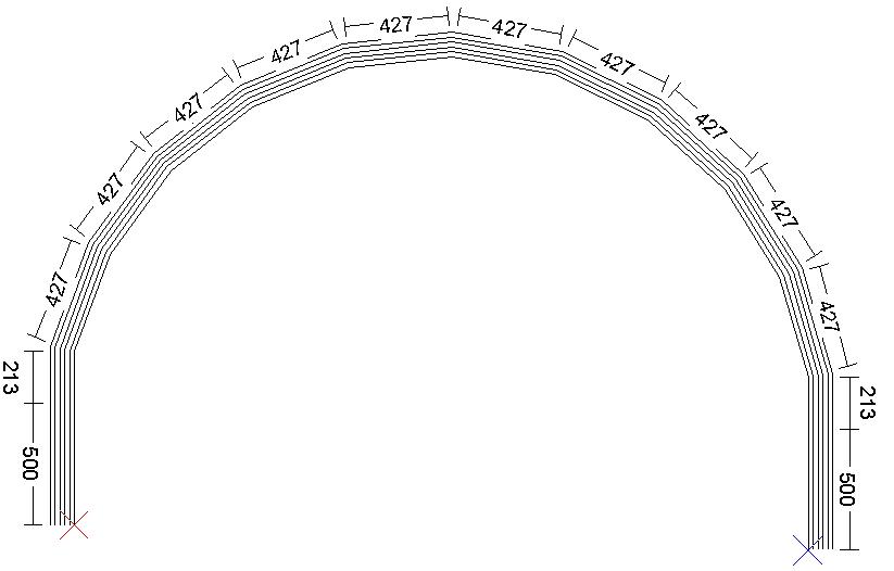
Starting from the red cross - 500 wall, curved wall (radius 1500, steps 10, angle 180), 500 wall.
NOTE - the more steps you use, the more rounding errors will occur. Notice the end of the wall (blue cross) is lower than the starting point (red cross). Adjust the length of the last piece of the curved wall (the 213 wide wall) until they line up.
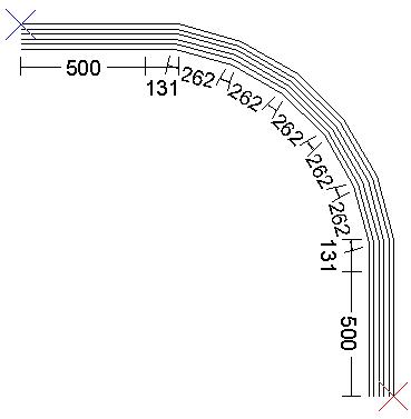
Starting from the red cross - 500 wall, curved wall (radius 1000, steps 5, angle -90), 500 wall.
Return to top.

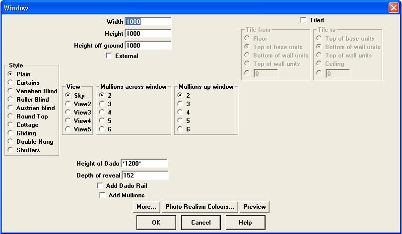
Add a flag window to your design in the same way as you would add any other wall component.
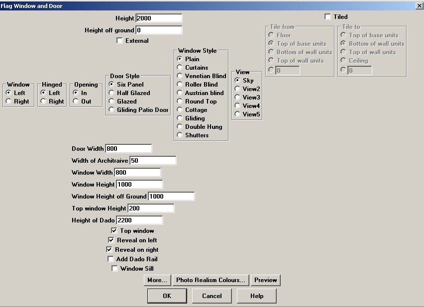
The majority of the options will be familiar from either the Wall or Window components. However there are a few extra options.
The flag window is only available as a wall component within the Walls layer, not as an internal wall.
Return to top.
Make sure you are in "Normal Mode" - click the "Normal Mode" button on the Utilities Window, or click "Mode" then "Normal".
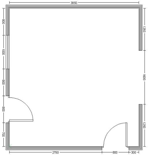
To draw this room, the sequence of events would be:
 |
Click the "Walls" layer button, top left of the screen. |
|
Wall. Change the width to 700. Click "OK". |
|
Door. 800 wide (default). Left-hand hinged, opening in to the room. Click "OK". |
|
Wall. Change the width to 800. Click "OK". |
|
Window. 1000 wide (default). Click "OK". |
|
Wall. Change the width to 800. Click "OK". |
|
Turn. Click "OK". |
|
Wall. Change the width to 3850. Click "OK". |
|
Turn. Click "OK". |
|
Wall. Change the width to 1250. Click "OK". |
|
Arch. Change the width to 1600. Click "OK". |
|
Wall. Change the width to 1250. Click "OK". |
|
Turn. Click "OK". |
|
Wall. Change the width to 300. Click "OK". |
|
Door. 800 wide (default). Left-hand hinged, opening in to the room. Click "OK". |
|
Wall. Change the width to 2750. Click "OK" |
|
Join. Click "OK". |
Return to top.